NAMIC Wiki:DTI:HelixDWI
This page shows how to use Teem command-line tools to create a synthetic DWI dataset in NRRD format, which can be used to verify a given piece of software's handling of the coordinate frames involved, especially the measurement frame.
Running these commands requires a version of Teem more recent than version 1.9.0, the version shipping with Slicer 2.6. However, the datasets can be downloaded from here without regenerating them.
Contents
Creating the gradient list
tend grads -n 12 \
 | unu pad -min 0 -1 -max M M -b pad -v 0 -o grads.txt
This generates a set of gradient directions, pre-pended with a zero vector (for a baseline image). The result should be the text file "grads.txt" with contents:
0 0 0
0.045864213 -0.97327703 -0.22500728
0.25820592 -0.47978204 0.83853376
-0.40941855 -0.2207699 0.88523281
0.90057635 -0.041144647 -0.43274629
0.9589954 -0.024969423 0.28231958
-0.53121203 -0.12678577 -0.8376987
-0.75857437 -0.61072785 0.22710435
-0.65501362 0.7005415 -0.28319383
0.56272566 0.69972253 0.44014561
0.10537088 -0.45475256 -0.88436252
-0.62760335 0.64766514 0.43202299
0.15000534 0.88426256 -0.44224218
Creating the synthetic tensor field
tend helix -s 29 30 31 -ip 0.1 0.3 0.6 -mp -0.8 0.1 0.4 -r 40 -o ten.nrrd
This program generates a tensor field where the anisotropy tensors are along a right-handed helix, with the tensors themselves displaying a particular kind of twist.
To make things interesting, the image orientation and measurement frames are set to something non-axis-aligned, via the "-ip 0.1 0.3 0.6" and "-mp -0.8 0.1 0.4" options respectively, and these determine the "space directions" and "measurement frame" fields. They can be inspected via:
unu head ten.nrrd
 NRRD0005
 # Complete NRRD file format specification at:
 # http://teem.sourceforge.net/nrrd/format.html
 type: float
 dimension: 4
 space: right-anterior-superior
 sizes: 7 29 30 31
 space directions: none (2.645253,5.951819,-2.267359) (-5.205479,3.287671,2.557078) (3.181617,0.707026,5.56783)
 centerings: ??? cell cell cell
 kinds: 3D-masked-symmetric-matrix space space space
 endian: big
 encoding: raw
 space origin: (-9.278346,-141.602085,-88.852048)
 measurement frame: (0.812155,0.353591,-0.464088) (-0.530387,0.116022,-0.839779) (-0.243094,0.928177,0.281768)
Creating the synthetic DWI data (.nhdr and .raw available)
First we have to invent a baseline T2 image:
tend helix -s 29 30 31 -ip 0.1 0.3 0.6 -mp -0.8 0.1 0.4 -r 50 \
 | tend anvol -a fa \
 | unu 2op x - 7000 -o b0.nrrd
This is a little silly- its just making a new tensor volume with a fatter radius ("-r 50" instead of "-r 40"), then measuring fractional anisotropy everywhere, multiplying it by 7000, then saving it out to a scalar nrrd volume.
Then, the DWI value simulation is done based on the baseline image and synthetic tensors:
tend sim -g grads.txt -r b0.nrrd -i ten.nrrd \
  -b 800 -t ushort -kvp -o dwi-D.nhdr
This results in a NRRD DWI header of the same form that is created for measured DWI scans:
- File:Dwi-D.nhdr: the detached NRRD header
- File:Dwi-D.raw: the single raw file (same directory as .nhdr file)
 NRRD0005
 # Complete NRRD file format specification at:
 # http://teem.sourceforge.net/nrrd/format.html
 content: (unsigned short)(???)
 type: unsigned short
 dimension: 4
 space: right-anterior-superior
 sizes: 13 29 30 31
 space directions: none (2.645253,5.951819,-2.267359) (-5.205479,3.287671,2.557078) (3.181617,0.707026,5.56783)
 centerings: ??? cell cell cell
 kinds: list space space space
 endian: big
 encoding: raw
 space origin: (-9.278346,-141.602085,-88.852048)
 measurement frame: (0.812155,0.353591,-0.464088) (-0.530387,0.116022,-0.839779) (-0.243094,0.928177,0.281768)
 data file: dwi-D.raw
 modality:=DWMRI
 DWMRI_b-value:=800
 DWMRI_gradient_0000:=0 0 0
 DWMRI_gradient_0001:=0.0458642 -0.973277 -0.225007
 DWMRI_gradient_0002:=0.258206 -0.479782 0.838534
 DWMRI_gradient_0003:=-0.409419 -0.22077 0.885233
 DWMRI_gradient_0004:=0.900576 -0.0411446 -0.432746
 DWMRI_gradient_0005:=0.958995 -0.0249694 0.28232
 DWMRI_gradient_0006:=-0.531212 -0.126786 -0.837699
 DWMRI_gradient_0007:=-0.758574 -0.610728 0.227104
 DWMRI_gradient_0008:=-0.655014 0.700541 -0.283194
 DWMRI_gradient_0009:=0.562726 0.699723 0.440146
 DWMRI_gradient_0010:=0.105371 -0.454753 -0.884363
 DWMRI_gradient_0011:=-0.627603 0.647665 0.432023
 DWMRI_gradient_0012:=0.150005 0.884263 -0.442242
Estimating and visualizing tensors
This uses "tend estim" to estimate tensors with linear-least-squares on the log(DWI), and then passes them to the Deft program for visualization:
tend estim -i dwi-D.nhdr -knownB0 false -B kvp -o - \
 | Deft_dti -i - -a fa -gsc 1200 -atr 0.65 \
  -fr 940.805 307.575 1025.14 -at 0 0 0 \
  -up -0.521774 -0.557152 0.646014 -rh -ar \
  -dn -164.709 -df 164.709 -fv 5.41056 -is 640 480
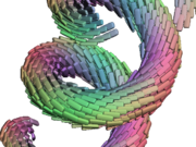
Because the camera and glyph parameters are set on the command-line, the following image should come up:
The following things should be noted:
- The region of anisotropy is helical. The spatial axis sizes were all unequal ("-s 29 30 31."), so if these are interpreted incorrectly (e.g. slow to fast instead of fast to slow), the anisotropic region will not appear as a simple helix.
- The helix is right-handed, like a DNA strand. As your right hand thumb moves along the axis of the helix, curling your fingers follows the path of the helix. If you see a left-handed helix, the handed-ness of your coordinate system is wrong.
- Along the surface of the helical path, the glyphs also rotate along a right-handed helix. If the tensors do not have this consistent surface-aligned appearance, there is something wrong with your handling of the measurement frame.
