Mapped Hexahedral Meshing
From NAMIC Wiki
Home < Mapped Hexahedral Meshing
Objective:
- Develop a tool for mapped meshing that will warp a template mesh onto a surface for a new subject
- Determine the limits that the warping algorithm will succeed and fail
- Apply these techniques to a sample of data to determine the reliability of the algorithm with respect to mesh quality
Progress:
- Warped meshing framework has been developed using VTK and ITK using a finite element approach
- VTK
- Support the reading and writing of meshes (vtkUnstructuredGrid) and surfaces (vtkPolyData)
- Distance measures between the deforming mesh and the subject surface
- Initial registration - Iterative Closest Point or Procrustes
- ITK
- Finite element framework used to warped the template mesh onto the subject surface
- VTK
- Registration made hierarchical to speed up the registration process
- Requires multiple template meshes to exist
- This is readily supported using the interactive meshing tools by changing the average edge length
- Subsequent meshes are initialized using a thin plate splines
- Parameters allowed to vary at each level of the registration
- Iterations
- Young's Modulus
- Convergence based on distance between the warped template and the subject surface
- User specified convergence threshold in mm
- Convergence can be based on average or maximum distance
- Boundary conditions can be applied
- Center of the mesh - Holds the eight nodes closest to the center of the mesh fixed
- External - Applies boundary conditions to the mesh as they fall within a user specified tolerance of the subject surface
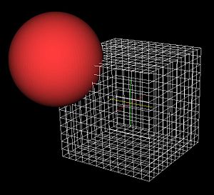
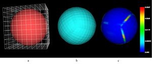
- Initial testing done by warping a cube mesh onto a sphere
- Evaluation:
- Distance between warped mesh and subject surface
- Mesh quality
- Evaluation:
To Do:
- Further evaluation on the phalanx bones of the hand
- Convert the code into a Slicer3 execution model program
- Develop additional Slicer3 execution model programs to support complete workflow
- Assignment of material properties based in image signal intensity
- Export to Abaqus format
- Determine if there are ways to improve the speed of the algorithm
Key Investigators:
- Iowa: Nicole Grosland, Vincent Magnotta, Ritesh Bafna
Links:
Execution Model Program Description:
- To be filled in once developed
This tool was developed as part of an NIH NA-MIC Collaboration Grant EB005973.
Program Usage:
- To be filled in once developed
Figures:


