Difference between revisions of "Projects/Diffusion/2007 Project Week Contrasting Tractography Measures/ROI Definitions"
| Line 78: | Line 78: | ||
====Cingulum Bundle==== | ====Cingulum Bundle==== | ||
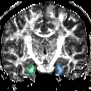
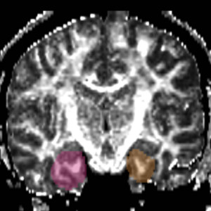
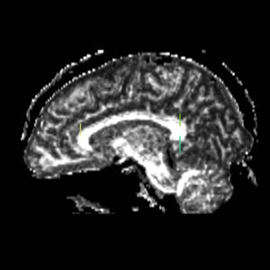
| − | ROI 1) on the superior side of the corpus, flush with the most anterior part of the corpus (based on sag view, but drawn on coronal view) | + | ROI 1) on the superior side of the corpus, flush with the most anterior part of the corpus (based on sag view, but drawn on coronal view) (Fig. 15 & 18) |
| − | <p>ROI 2) on the first coronal slice where the L & R corpus connect, on the superior side of the corpus.</p> | + | <p>ROI 2) on the first coronal slice where the L & R corpus connect, on the superior side of the corpus. (Fig. 16 & 18) </p> |
| − | <p>ROI 3) on the first coronal slice where the L & R corpus connect, on the inferior side of the corpus.</p> | + | <p>ROI 3) on the first coronal slice where the L & R corpus connect, on the inferior side of the corpus. (Fig. 16 & 18) </p> |
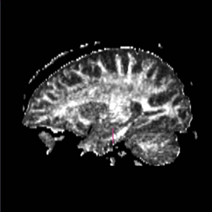
| − | <p>ROI 4) on the first coronal slice where the middle cerebellar peduncle is present.</p> | + | <p>ROI 4) on the first coronal slice where the middle cerebellar peduncle is present.(Fig. 17 & 19) </p> |
::ROI 1: Left(7) - Right(8) | ::ROI 1: Left(7) - Right(8) | ||
| Line 89: | Line 89: | ||
[[Image:cing_roi1.png|left|thumb|300px|Figure 15. Coronal View of Cingulum Bundle ROI 1, Left and Right]] [[Image:cing_roi23.png|left|thumb|300px|Figure 16. Coronal View of Cingulum Bundle ROI's 2 & 3, left and right]][[Image:cing_roi4.png|left|thumb|300px|Figure 17. Coronal View of Cingulum Bundle ROI 4, left and right]] | [[Image:cing_roi1.png|left|thumb|300px|Figure 15. Coronal View of Cingulum Bundle ROI 1, Left and Right]] [[Image:cing_roi23.png|left|thumb|300px|Figure 16. Coronal View of Cingulum Bundle ROI's 2 & 3, left and right]][[Image:cing_roi4.png|left|thumb|300px|Figure 17. Coronal View of Cingulum Bundle ROI 4, left and right]] | ||
| + | |||
| + | |- | ||
| + | | | ||
[[Image:Cing1ROIs.png|left|thumb|300px|Figure 18. Cingulum Bundle ROI's 1, 2, and 3]] [[Image:Cing2ROIs.png|left|thumb|300px|Figure 19. Cingulum Bundle ROI 4]] | [[Image:Cing1ROIs.png|left|thumb|300px|Figure 18. Cingulum Bundle ROI's 1, 2, and 3]] [[Image:Cing2ROIs.png|left|thumb|300px|Figure 19. Cingulum Bundle ROI 4]] | ||
Revision as of 18:50, 27 July 2007
Home < Projects < Diffusion < 2007 Project Week Contrasting Tractography Measures < ROI DefinitionsContents
Boundaries for the ROI's, mainly using FA maps & color by orientation, followed by the color coding of the labelmaps.
|
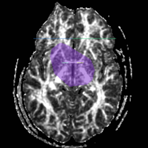
This page describes the definition of the regions of interest for five fiber bundles: the Internal Capsule, the Uncinate Fasciculus, the Fornix, the Arcuate Fasciculus and the Cingulum Bundle. Seed points were defined using a two ROIs approach. Each ROI was drawn on FA and color by orientation maps according to the criteria defined below: IC - Internal CapsuleROI 1) We found the anterior commisure in the axial view (Fig.1) and drew ROI on coronal slice on each side on midsag line |
|
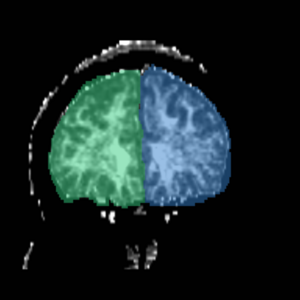
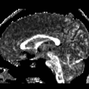
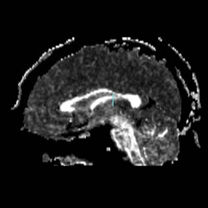
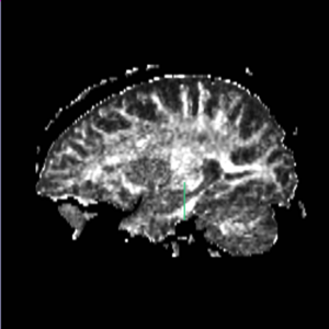
Top boundary for ROI 1: Caudate/putamen line Bottom boundary for ROI 1: draw entire plane of AC (Fig.1); IC is only superior to AC line. ROI 2) go to the anterior most point of the corpus collosum according to sagittal view (Fig 3). Draw ROI so it covers entire (left or right) hemisphere of brain on the perpendicular Coronal Slice (Fig 4). |
|
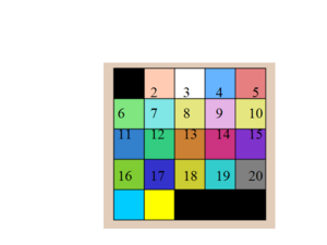
The color coding of the resulting ROIs is as follows:
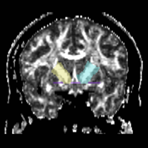
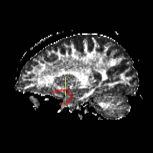
unc - Uncinate FasciculusFind the most prominant (central) slice of the fornix according to sagittal view (Fig. 5). Go one slice anterior to the most anterior point of the fornix and draw Left and Right ROI 1 and ROI 2 (Fig. 6). The color coding of the resulting ROIs is as follows:
|
|
|
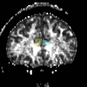
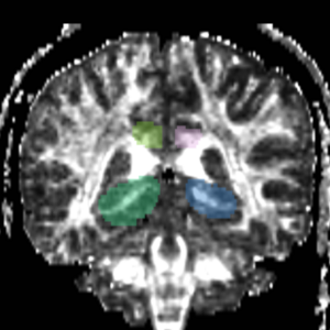
FornixROI 1) on Coronal view, the first slice where the middle cerebellar peduncles are present ROI 2) posterior to ROI 1; large blobs drawn on coronal view where the middle cerebellar peduncle is clearly connected at bottom of slice
|
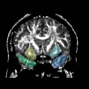
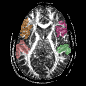
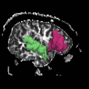
Arcuate FasciculusThese labelmaps ('caseD00XXX-FS-arcuate-final.nhdr') were created using automatic gray matter parcellation in Freesurfer and coregistered in Slicer to corresponding DTI dataset. The labelmaps were dilated in Slicer to increase coverage of gray matter.
|
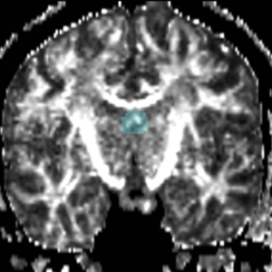
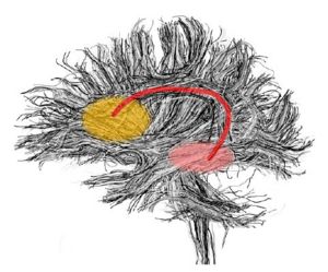
Cingulum BundleROI 1) on the superior side of the corpus, flush with the most anterior part of the corpus (based on sag view, but drawn on coronal view) (Fig. 15 & 18) ROI 2) on the first coronal slice where the L & R corpus connect, on the superior side of the corpus. (Fig. 16 & 18) ROI 3) on the first coronal slice where the L & R corpus connect, on the inferior side of the corpus. (Fig. 16 & 18) ROI 4) on the first coronal slice where the middle cerebellar peduncle is present.(Fig. 17 & 19)
|
Return to Contrasting Tractography Project page
