Difference between revisions of "Slicer Interactive Module"
| Line 43: | Line 43: | ||
* Commented unneded functionality in BuildingBlock/vtkKWMimxViewWindow - we are using Slicer's 3D window instead and will set the renderWindowWidget after instantiation. | * Commented unneded functionality in BuildingBlock/vtkKWMimxViewWindow - we are using Slicer's 3D window instead and will set the renderWindowWidget after instantiation. | ||
* Added vtkKWMimxMainWindow::SetRenderWidget() | * Added vtkKWMimxMainWindow::SetRenderWidget() | ||
| + | * Question: has MimxViewWindow been abandoned? It seems that MainWindow has same functionality. | ||
Revision as of 15:23, 7 May 2008
Home < Slicer Interactive ModuleThe scope of this subproject is to develop a Slicer3 module for Finite Element modeling. Our approach is to adapt the process and source code from a standalone Finite Element Mesh generation program developed by the MIMX Group at the University of Iowa.
Contents
Standalone Program
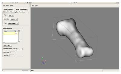
The IaFeMesh application creates an established workflow consisting of multiple steps:
- read imagery file
- create surface from imagery
- create FE mesh bounding box from the bounds of the surface
- refine the FE bounding box
- generate a mesh using projection from the bounding box
The above properties are accomplished through customer KKWidgets which manage the user through workflow using a custom tabbed notebook with image, surface, FE Mesh, and FE Mesh Quality tabs. Under each category, the user works with the corresponding category of data as they perform the workflow that starts with a source image stack and results in a corresponding Mesh of the imaged object.
The standalone program manages surfaces, bounding boxes, and meshes created by the user in linked lists which are updated and displayed through a directly connected GUI.
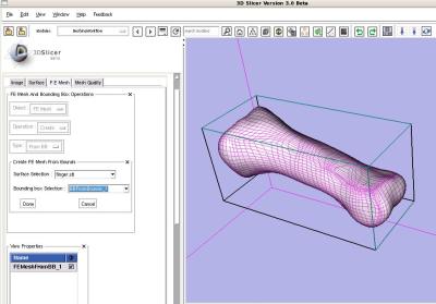
MeshingWorkflow Slicer Module
An interactive module has been added to Slicer called the "MeshingWorkflow Module". This module performs the same multiple steps as the standalone FE application. The vast majority of the source code from the original application has been re-used without modification.
Migrating the intermediate steps to MRML
The standalone workflow code uses local lists of surfaces, bounding boxes, and meshes to store intermediate workflow state. This allows the user to browse forward and backward through the workflow as needed and is an efficient workflow model. A drawback of this technique (from the slicer integration perspective) is that this information is not stored in the MRML tree during the workflow process.
Therefore, modifications were required to the storage list classes to synchronize with the MRML tree.
Steps to Ingest standalone application code for a Slicer module
- Adapt CMakeLists files from stand-alone to module versions. Keep old module cmake configuration files as an example how to add proper wrapping and inter-library references.
- Debug support libraries (Common, Widgets, Adapter, Filter, BuildingBlock, etc.) one at a time until you have Compiled each supporting library separately.
Coding change notes for Slicer integration of standalone IaFeMesh source code
- Commented unneded functionality in BuildingBlock/vtkKWMimxViewWindow - we are using Slicer's 3D window instead and will set the renderWindowWidget after instantiation.
- Added vtkKWMimxMainWindow::SetRenderWidget()
- Question: has MimxViewWindow been abandoned? It seems that MainWindow has same functionality.

