Difference between revisions of "NA-MIC/Projects/Collaboration/MGH RadOnc"
| Line 17: | Line 17: | ||
|[[Image:RadOnc_HN5_deformable.png|thumb|380px|Deformable registration]] | |[[Image:RadOnc_HN5_deformable.png|thumb|380px|Deformable registration]] | ||
|} | |} | ||
| + | |||
| + | (I don't know why the wiki didn't like the | ||
===Adaptive RT for Thorax=== | ===Adaptive RT for Thorax=== | ||
Revision as of 20:40, 29 January 2009
Home < NA-MIC < Projects < Collaboration < MGH RadOnc
Adaptive RT for Head and Neck
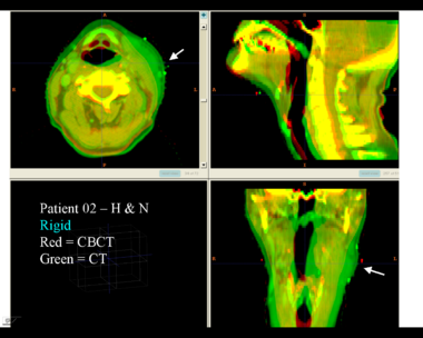
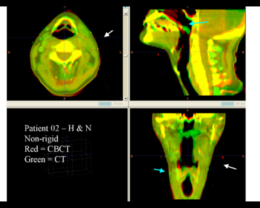
This example shows the anatomic change in head and neck cancer. The pre-treatment scan is in green, and the mid-treatment scan is in red. The image on the left is the rigid registration.
Here is another pertinent example for head and neck. In axial view, there appears to be some weight loss. Note the change in positioning of the mandible, and also the twisting of the cervical spine between scans. Also note the strong CT artifacts caused by dental fillings.
| File:RadOnc HN5 deformable.png |
(I don't know why the wiki didn't like the
Adaptive RT for Thorax
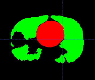
This example shows the anatomic change in head and neck cancer. The pre-treatment scan is in green, and the mid-treatment scan is in red. The image on the left is the rigid registration.
Here is another pertinent example for head and neck. In axial view, there appears to be some weight loss. Note the change in positioning of the mandible, and also the twisting of the cervical spine between scans. Also note the strong CT artifacts caused by dental fillings.
| File:RadOnc HN5 deformable.png |
General Discussion of Registration
Deformable registration is still not as reliable as it should be. Image acquisition has residual artifacts which cause unrealistic deformations. Registration algorithms are not always robust, and require experimentation and tuning. Validation of registration results is not easy, since there are inadequate tools. Temporal regularization is generally not done, because of slow algorithms and large memory footprints. And so on.
4D-CT Registration in Thorax
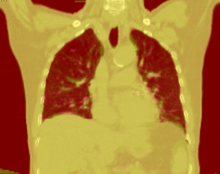
Thorax is a special case. Patient images are acquired using 4D-CT, and radiation dose can computed for 3D volumes at each breathing phase. The volumes are aligned using deformable registration, and radiation dose is accumulated in a reference phase (e.g. exhale). Ideally this procedure is repeated to perform 4D treatment plan optimization.
The sliding of the lungs against the chest wall is difficult to model. We sometimes segment the images at the pleural boundary. This allows us to separate the moving set of organs from the non-moving set, which are registered separately. Ideally we would always do this, but segmentation is manual and therefore we usually skip this step.
If you ignore the pleural boundary, registration of 4D-CT is considered "easy".
- Single-session imaging, so patient is already co-registered
- Single-session imaging, so no anatomic change
- High contrast of vessels against lung parenchema
State of the art is probably around 2-3 mm RMS error for point landmarks.
Progress
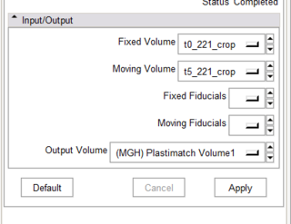
- Working CLP program
- Got fiducials from Slicer -- Wow!
- Preliminary CTest interface
- DicomRT contour conversion
Todo
- Convert from CLP to scriptable or loadable module
- Improved visualization of registration output
- Improved interactivity of fiducials
- Export of deformed contours to DicomRT
Interactive Segmentation
Rad Onc departments use interactive segmentation every day for both research and patient care. Prior to treatment planning, the target and critical structures are delineated in CT. The current state of the art is manual segmentation in axial view. A outline tool, used delineate the boundary, is generally prefered over a paintbrush tool that fills pixels. Commercial products generally support some subset of the following tools to assist the operator.
- contour interpolation between slices
- boundary editing
- mixed axial/coronal/sagittal drawing
- livewire or intelligent scissors
- drawing constraints (e.g. constraints on volume overlap/distance)
- post-processing tools to nudge or smooth the boundary
There are many opportunities for using computer vision algorithms to improve interactive segmentation. For example, using prior models of shape and intensity to improve interpolation.
