Difference between revisions of "2012 Summer Project Week:Open source electromagnetic trackers using OpenIGTLink"
(Created page with '__NOTOC__ <gallery> Image:Dry0030.png|Stylized image of three orthogonal coils used in 6-DOF electromagnetic tracker sensor </gallery> ==Key Investigators== * Retired: Peter Tr…') |
|||
| (11 intermediate revisions by the same user not shown) | |||
| Line 3: | Line 3: | ||
<gallery> | <gallery> | ||
Image:Dry0030.png|Stylized image of three orthogonal coils used in 6-DOF electromagnetic tracker sensor | Image:Dry0030.png|Stylized image of three orthogonal coils used in 6-DOF electromagnetic tracker sensor | ||
| + | Image:Dry_elphel_model_1_rcvr_coils.jpg|Handmade assembly of three solenoidal coils; each solenoid is 11 millimeters long | ||
| + | Image:Dry0002_256.png|One plane of 256x256x256 NRRD, pixel = X.xor.Y.xor.Z | ||
</gallery> | </gallery> | ||
| Line 14: | Line 16: | ||
<h3>Objectives</h3> | <h3>Objectives</h3> | ||
| + | One goal of this open-source electromagnetic tracker project is to extend the tracker simulators in OpenIGTLink, by replacing the simulated position and orientation data with real data from real sensors using real hardware, all open-sourced. | ||
| + | Another goal of this project, is to provide an open forum for tracker designers to discuss the technology in all its aspects. Open-source tracker projects provide a common basis for discussion among tracker designers who are otherwise trapped behind proprietary walls. | ||
| + | |||
| + | The physics of electromagnetic trackers only just works. Tracker designers are continually struggling to get enough signal/noise from a small-enough sensor at a large-enough distance for a particular application. Magnetic-field distortion adds to the challenges. | ||
| + | |||
| + | Another goal of this project, is to enable researchers to simulate trackers for themselves, to better understand the limits imposed by the physics. | ||
| + | |||
| + | Another goal of this project, is to provide opportunities to gain experience on simple, unusual, and state-of-the-art analog hardware, digital hardware, digital-signal-processing algorithms, electromagnetic modeling, and position-calculation algorithms. | ||
| Line 26: | Line 36: | ||
<h3>Approach, Plan</h3> | <h3>Approach, Plan</h3> | ||
| − | + | Pete's plan for the project week, is to demonstrate a hand-built prototype 6DOF tracker sending position and orientation data over OpenIGTLink to Slicer, | |
| + | and to discuss what to do next. | ||
| + | |||
| + | Pete also plans to test and debug C programs to generate NRRD images from numerical or analytic data. The intent, is to test feasibility of using | ||
| + | Slicer to visualize magnetic field models of coils. | ||
| − | + | Pete also plans to start writing C code to characterize the coils from measured data. | |
</div> | </div> | ||
| Line 35: | Line 49: | ||
<h3>Progress</h3> | <h3>Progress</h3> | ||
| − | |||
| + | Pete's published work to date is on | ||
| + | [[Open Source Electromagnetic Trackers|Open Source Electromagnetic Trackers]] | ||
| + | and on [[http://home.comcast.net/~traneus http://home.comcast.net/~traneus]]. | ||
| + | |||
| + | [[http://home.comcast.net/~traneus/dry_model_1_isca_tracker_photos.htm Photos]], | ||
| + | [[http://home.comcast.net/~traneus/dry_model_1_isca_tracker_block_diagram.png block diagram]], | ||
| + | [[http://home.comcast.net/~traneus/dry_model_1_isca_tracker_electronics.htm electronics]], | ||
| + | [[http://home.comcast.net/~traneus/dry_model_1_isca_tracker_magnetics.htm magnetics]] of hand-built first | ||
| + | [[http://home.comcast.net/~traneus/dry_emtrackertricoil.htm 6DOF]] prototype. | ||
| + | |||
| + | Pete had many good, useful, and broadening conversations. | ||
| + | |||
| + | Pete made a NRRD that Slicer 3 accepted and displayed; see image above for one plane. | ||
| + | |||
| + | Pete demonstrated a hand-built prototype 6DOF EM tracker communicating over OpenIGTLink to Slicer 3 on the same computer and to Slicer 4 over the network | ||
| + | on another computer. | ||
| + | |||
| + | Pete did no work on coil characterization software. | ||
| + | |||
| + | Pete wrote first cut at | ||
| + | HOWTO build a 6DOF tracker without building electronics: | ||
| + | |||
| + | 0. Use PC running favorite OS as computer. | ||
| + | |||
| + | 1. Install extra sound card able to drive stereo speakers. | ||
| + | |||
| + | 2. Program sound card to generate sinewaves into speaker channels: | ||
| + | 1875.00 Hz sinewave out left channel | ||
| + | (1406.25 Hz sinewave + 2343.75 Hz sinewave) out right channel | ||
| + | |||
| + | 3. Wire up transmitter coils and tuning capacitors: | ||
| + | Left channel drives Y transmitter coil through tuning capacitor. | ||
| + | Right channel drives X coil and Z coil through separate capacitors. | ||
| + | |||
| + | 4. Choose and purchase data-acquisition (DAQ) card for PC | ||
| + | (This will probably be the most-expensive part of the tracker): | ||
| + | 6 or more analog-to-digital converters (ADCs) | ||
| + | 24-bit ADCs | ||
| + | 48 KSPS or 96 KSPS | ||
| + | |||
| + | 5. Learn how to read ADC data from DAQ card. | ||
| + | |||
| + | 6. Wire up transmitter current-sense resistors to three ADCs. | ||
| + | |||
| + | 7. View waveforms from these three ADCs. | ||
| + | |||
| + | 8. DFT these three ADCs as in dry0340.c . | ||
| + | |||
| + | 9. Adjust tuning capacitors to peak transmitter coil currents: | ||
| + | 1406.25 Hz X coil current | ||
| + | 1875.00 Hz Y coil current | ||
| + | 2343.75 Hz Z coil current | ||
| + | Don't worry if a little of other frequencies show up in currents. | ||
| + | |||
| + | 10. Wire up receiver coils to three more ADCs. | ||
| + | |||
| + | 11. View waveforms from all six ADCs. | ||
| + | |||
| + | 12. DFT all six ADCs as in dry0340.c . | ||
| + | |||
| + | 13. Implement HFluxPerI calculation as in dry0340.c . | ||
| + | |||
| + | 14. Implement Raab's solution as in dry0340.c . | ||
| + | |||
| + | 15. Track! | ||
| + | |||
| + | Just in case no existing commercial or open-source DAQ boards are suitable, Pete intends to design a simple open-source 8-ADC USB-based board (with 2048-sample FIFO buffer) that would be suitable. | ||
</div> | </div> | ||
| Line 44: | Line 124: | ||
==Delivery Mechanism== | ==Delivery Mechanism== | ||
| − | |||
| − | |||
| − | |||
| − | |||
| − | |||
| − | |||
| − | |||
| − | |||
| − | |||
==References== | ==References== | ||
</div> | </div> | ||
Latest revision as of 11:05, 22 June 2012
Home < 2012 Summer Project Week:Open source electromagnetic trackers using OpenIGTLink
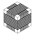
Stylized image of three orthogonal coils used in 6-DOF electromagnetic tracker sensor
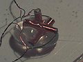
Handmade assembly of three solenoidal coils; each solenoid is 11 millimeters long

One plane of 256x256x256 NRRD, pixel = X.xor.Y.xor.Z


Key Investigators
- Retired: Peter Traneus Anderson
- NA-MIC: Tina Kapur, Sonia Pujol
Objectives
One goal of this open-source electromagnetic tracker project is to extend the tracker simulators in OpenIGTLink, by replacing the simulated position and orientation data with real data from real sensors using real hardware, all open-sourced.
Another goal of this project, is to provide an open forum for tracker designers to discuss the technology in all its aspects. Open-source tracker projects provide a common basis for discussion among tracker designers who are otherwise trapped behind proprietary walls.
The physics of electromagnetic trackers only just works. Tracker designers are continually struggling to get enough signal/noise from a small-enough sensor at a large-enough distance for a particular application. Magnetic-field distortion adds to the challenges.
Another goal of this project, is to enable researchers to simulate trackers for themselves, to better understand the limits imposed by the physics.
Another goal of this project, is to provide opportunities to gain experience on simple, unusual, and state-of-the-art analog hardware, digital hardware, digital-signal-processing algorithms, electromagnetic modeling, and position-calculation algorithms.
Approach, Plan
Pete's plan for the project week, is to demonstrate a hand-built prototype 6DOF tracker sending position and orientation data over OpenIGTLink to Slicer, and to discuss what to do next.
Pete also plans to test and debug C programs to generate NRRD images from numerical or analytic data. The intent, is to test feasibility of using Slicer to visualize magnetic field models of coils.
Pete also plans to start writing C code to characterize the coils from measured data.
Progress
Pete's published work to date is on Open Source Electromagnetic Trackers and on [http://home.comcast.net/~traneus].
[Photos], [block diagram], [electronics], [magnetics] of hand-built first [6DOF] prototype.
Pete had many good, useful, and broadening conversations.
Pete made a NRRD that Slicer 3 accepted and displayed; see image above for one plane.
Pete demonstrated a hand-built prototype 6DOF EM tracker communicating over OpenIGTLink to Slicer 3 on the same computer and to Slicer 4 over the network on another computer.
Pete did no work on coil characterization software.
Pete wrote first cut at HOWTO build a 6DOF tracker without building electronics:
0. Use PC running favorite OS as computer.
1. Install extra sound card able to drive stereo speakers.
 2. Program sound card to generate sinewaves into speaker channels:
 1875.00 Hz sinewave out left channel
 (1406.25 Hz sinewave + 2343.75 Hz sinewave) out right channel
 3. Wire up transmitter coils and tuning capacitors:
 Left channel drives Y transmitter coil through tuning capacitor.
 Right channel drives X coil and Z coil through separate capacitors.
 4. Choose and purchase data-acquisition (DAQ) card for PC
 (This will probably be the most-expensive part of the tracker):
 6 or more analog-to-digital converters (ADCs)
 24-bit ADCs
 48 KSPS or 96 KSPS
5. Learn how to read ADC data from DAQ card.
6. Wire up transmitter current-sense resistors to three ADCs.
7. View waveforms from these three ADCs.
8. DFT these three ADCs as in dry0340.c .
 9. Adjust tuning capacitors to peak transmitter coil currents:
 1406.25 Hz X coil current
 1875.00 Hz Y coil current
 2343.75 Hz Z coil current
 Don't worry if a little of other frequencies show up in currents.
10. Wire up receiver coils to three more ADCs.
11. View waveforms from all six ADCs.
12. DFT all six ADCs as in dry0340.c .
13. Implement HFluxPerI calculation as in dry0340.c .
14. Implement Raab's solution as in dry0340.c .
15. Track!
Just in case no existing commercial or open-source DAQ boards are suitable, Pete intends to design a simple open-source 8-ADC USB-based board (with 2048-sample FIFO buffer) that would be suitable.