Difference between revisions of "Projects:RegistrationLibrary:RegLib C43"
| Line 35: | Line 35: | ||
=== Procedure / Pipeline === | === Procedure / Pipeline === | ||
| − | #Open case scene file or import image data: | + | #Open case scene file or import image data: RegLib_C43_SlicerScene1.mrml |
| − | # | + | #Preprocess segmentation for building surface models |
| − | # | + | ##we need to fill in the interior of the vertebral body, we use the morphological closing (Editor) and hole filling module |
| + | ##go to Editor | ||
| + | ## select the intact_seg volume as label map to edit | ||
| + | ##Select diliation tool, click on 8-neighbor checkbox for connectiviy, click ''Apply'' | ||
| + | ##Select erosion tool, click on 8-neighbor checkbox for connectiviy, click ''Apply'' | ||
| + | |||
| + | agittal view and note the inverted axis orientation | ||
#Flip axis | #Flip axis | ||
##Go to the [http://www.slicer.org/slicerWiki/index.php/Modules:Data-Documentation-3.6 Data module] | ##Go to the [http://www.slicer.org/slicerWiki/index.php/Modules:Data-Documentation-3.6 Data module] | ||
Revision as of 20:11, 12 August 2011
Home < Projects:RegistrationLibrary:RegLib C43Back to ARRA main page
Back to Registration main page
Back to Registration Use-case Inventory
Contents
v3.6.3  Slicer Registration Library Case 43: Surface registration of 3D vertebra models
Input

|

|

|
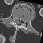
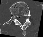
| baseline model | follow-up model: contains defect and is acquired in different orientation |
Modules
- Slicer 3.6.3 recommended modules: BRAINSFit
Objective / Background
This dataset contains 3D modls obtained from in vitro CT of a human vertibral body segment (L4) before and after regional damage. Goal is to align the two models to study in detail the local changes that occurred and obtain estimates of structural integrity loss. Because the two orientations differ widely between acquisitions image-to-image registration has reduced robustness due to difficulty in initializing a good starting condition. Surface registration on the other hand is very robust toward strong difference in pose and he ce makes a good candidate for obtaining a fully automated first alignment.
Keywords
CT, spine cancer, vertebrae, surface registration, 3D models, model registration
Issues Challenges
- two images have very different spatial origins (as defined in original DICOM header): recenter first
- the initial segmentation obtained by thresh Leung the CT image is very sparse and not suitable for model generation as is. Morphological operators will have to be applied to generate a meaningful label map to build models from.
- the two models differ significantly in rotational alignment
Input Data
- fixed: segmented CT , 0.6 x 0.6 x 0.40 mm voxel size, axial; 292 x 292 x 91 unsigned short image
- moving: segmented CT , 0.6 x 0.6 x 0.40 mm voxel size, axial; 512 x 512 x 107 unsigned short image
Procedure / Pipeline
- Open case scene file or import image data: RegLib_C43_SlicerScene1.mrml
- Preprocess segmentation for building surface models
- we need to fill in the interior of the vertebral body, we use the morphological closing (Editor) and hole filling module
- go to Editor
- select the intact_seg volume as label map to edit
- Select diliation tool, click on 8-neighbor checkbox for connectiviy, click Apply
- Select erosion tool, click on 8-neighbor checkbox for connectiviy, click Apply
agittal view and note the inverted axis orientation
- Flip axis
- Go to the Data module
- right-click on the Scene node and select "Insert Transform Node" from the menu
- select the newly created transform node, then in the MRML Node Inspector below, rename it to "Xf0_AxialFlip"
- select the "T10intact" node and drag it inside/on top of the "Xf0_AxialFlip" node
- ensure you have T10intact selected for background and the fade slider set on background (B) so you can see changes happening.
- Go to the Transforms module
- Select "Xf0_AxialFlip" from the Transform Node menu
- In the 4x4 matrix displayed, click in the field containing the "1.0000" in row 3 and column 3.
- hit Return key to activate editing
- change the number to -1. Hit Enter.
- you should see the image flip in the sagittal and coronal slice views
- Go to the Data module
- Crop Volumes
- Go to the Crop Volume module
- select "T10intact" as Input Volume; select "Create new MRML ROI Node" in the ROI menu, select "create new volume" in the Output Volume" menu
- you should see a small blue rectangle in all 3 views. Click in the views to expand the region to contain only the L4 vertebra (body and processes)
- when finished, click on Do ROI resample
- go to back to the Data module and change the name of the new "SubVolume" to "T10intact_crop"
- delete the ROI nodes (right click: delete node)
- repeat the same for the "T10defect" image
- Registration
- Go to the BRAINSfit module
- 'Presets: select the "BRAINSFit_Affine" from the parameter set menu. See here for a guide on how to Load/Save Registration Parameter Presets]]
- otherwise select the following parameters:
- Fixed Image Volume: :T10intact_crop ; Moving: T10defect_crop
- check boxes for "Moments align", Include Rigd registr. phase , Include ScaleVersor3D, include Affine
- Slicer Linear Transform: select "create new transform", rename to "Xf1_Affine" or similar
- leave rest at defaults. Click Apply
- registration should take ~ 10 secs.
- use fade slider to verify alignment; compare with result snapshots shown below.
- Go to the BRAINSfit module
Registration Results
Download
- Data
- Presets

